Water hammer is part of the larger subject of transient flow or surge analysis. It is the special case when there is a sudden change in flow velocity. Usually this occurs when a valve closes quickly. Water hammer can generate very high pressure transients which could burst a pipe and can generate pipeline vibrations. The magnitude of the water hammer pressure rise can be calculated using the Joukowsky equation which is
P=ρCU (Pa)
Where
P is the change in pressure
ρ is the fluid density
U is the change in fluid velocity
C is the sonic velocity in the pipe
The sonic velocity is the speed of sound in the pipe and is determined by a modified hooks law formula which takes into account the stiffness of the fluid and the pipe wall.
Where
K Bulk modulus of fluid
E Young’s modulus of pipe material
e Wall thickness of pipe
The sonic velocity is also the speed at which the pressure waves generated by water hammer travel in the pipe.
For water in very stiff pipes the sonic speed could be as high as 1480 m/s. But in some plastic pipe the wave speed can be lower than 200 m/s.
The bulk modulus (k) of water is 2.19x10⁹ Pa however this assumes that the water has no air bubbles in it. Often microscopic size bubbles can be seen suspended in the fluid. This can make a significant difference to the effective bulk modulus and so to the sonic speed. Often with water hammer sub atmospheric pressure and cavitation can also occur (as explained below). This can liberate dissolved air from the water which forms air bubbles reducing the effective bulk modulus and so reducing the wave speed.
Valve Closure Example of Water Hammer.
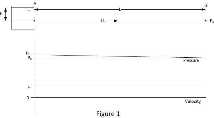
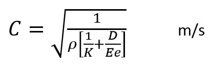
Figure 1 shows the initial conditions in the pipe. The pipe inlet at position A is connected to a header tank which provides the pressure P1 to drive the flow in the pipe. The other end of the pipe at position B is open to atmosphere and its pressure is P0
P1=ρgh+P0
The length of the pipe is L.
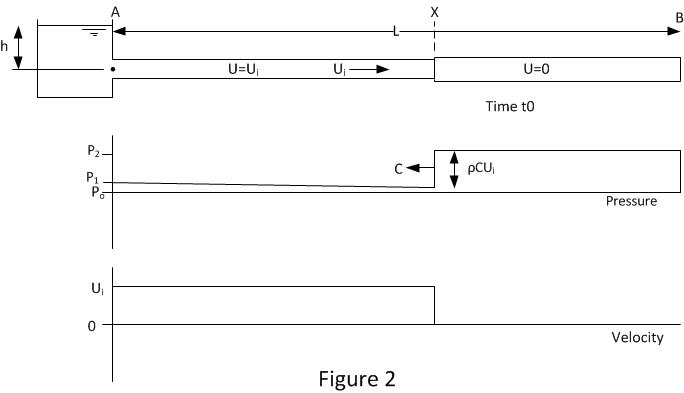
Figure 2 shows the pipe and flow conditions just after the pipe end at B has been instantaneously closed at time t0. A pressure wave at position X is traveling up the pipe with velocity C (the sonic velocity). The pressure rise across the wave is ρCU (Joukowsky equation). Upstream of position X the velocity is the initial velocity Ui. Downstream of X the velocity is 0.
Between X and B the fluid will be compressed and the pipe will be expanded. The rate of pipe volume change and fluid compression is the same as the flow rate upstream of X.
Figure 3 shows the conditions when the pressure wave reaches position A at time t1. The pipeline pressure has been raised by ρCUi and the fluid velocity is 0 throughout. This condition is unstable as the pipe inlet pressure is set by the head of fluid in the inlet tank h. So now the fluid needs to move in the reverse direction from the high pressure pipe into the lower pressure tank. This induces the first wave reflection and it occurs at time t1.
Where t1=t0+L/C
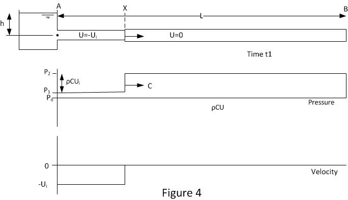
Figure 4 shows the conditions after the first reflection. The pressure wave is at position X and is traveling down the pipe with velocity C. The fluid between positions A and X is traveling in the reverse direction with velocity –Ui. The drop in pressure across the wave front is ρC(-Ui).
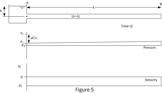
Figure 5 shows the conditions when the pressure wave reaches position B at time t2. The whole of the pipeline pressure has been reduced and the fluid velocity is -Ui throughout.
It should be noted there will be a small negative pressure gradient between A & B. This is required to overcome friction between the fluid and pipe as the flow is in the opposite direction. The magnitude of this pressure gradient will usually be significantly smaller than that generated by the change in velocity (Joukowsky equation). This friction gradient is exaggerated in the figure in comparison to water hammer effect for demonstration purposes.
As the end of the pipe at B is closed, this condition is unstable as there is fluid available to sustain the flow. This induces the second wave reflection at time t2.
Where t2=t1+L/C or t2=t0+2L/C.
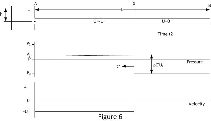
Figure 6 shows the conditions after the second reflection. The pressure wave is at position X and it is traveling up the pipe with velocity C’. The fluid between positions A and X is still traveling in the reverse direction with velocity –Ui. The fluid between X and B has been stopped.
The drop in pressure across the wave front is ρC’(-Ui). It should be noted that in this case the wave speed or sonic velocity has been changed from C to C’. C’ may be the same or less than C, it depends on the minimum allowable pressure P3. Negative absolute pressures are not possible. The minimum pressure in the pipe line cannot be less than the vapour pressure of fluid and often the minimum pressure is higher than the vapour pressure because there is dissolved gas in the fluid which comes out of solution as the pressure is reduced. When cavitation occurs or gas comes out of solution the bulk modulus of fluid is reduced form K to K’. It is this reduction bulk modulus that allows the sonic speed to reduce from C to C’ .So all depending on minimum possible pressure the magnitude of C’ will adjust its self so that P3 is not lower than minimum possible pressure.
The formulas for wave speed and the Joukowsky equation are still valid when cavitation occurs but the bulk modulus will have reduced so ensuring consistency in the equations and no impossible pressures.
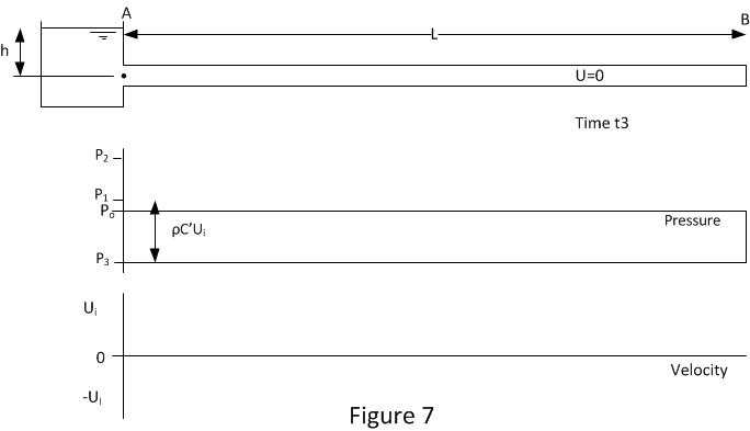
Figure 7 shows the conditions when the pressure wave reaches position A at time t3. The whole of the pipeline pressure has been reduced to P3 and the fluid velocity is 0 throughout. This condition is unstable as the pipe inlet pressure set by the head of fluid in the inlet tank h is higher than the pipe pressure so now the fluid needs to move into the pipe from the header tank. This induces the third wave reflection and it occurs at time t3.
Where t3=t2+L/C’ or t3=t0+2L/C+L/C’
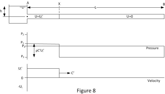
Figure 8 shows the conditions after the third reflection. The pressure wave is at position X, its traveling down the pipe with velocity C’. The fluid between positions A and X is still traveling in the normal direction with velocity Ui’. The fluid between X and B is stopped. The velocity in section A to X is shown as Ui’ where Ui’ is slightly less than Ui. By this stage the process has undergone 3 reflections and at every stage some energy is lost so over time the magnitude of the pressure waves and velocities are reducing.
The sonic wave velocity is still the reduced velocity C’ as shown in figure 8. But if previously air or vapour had been liberated from the fluid then the vapour will be re-condense and gas bubbles will reduce in size and may start to go back into solution.
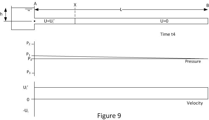
Figure 9 shows the conditions when the pressure wave reaches position B at time t4. As can be seen this is almost identical to the conditions shown in figure 1. The main difference is the velocity Ui’ is a little lower than the original Ui. As the end of the pipe is closed there is nowhere for the fluid at B to go. So this will induce the final reflection at time t4 and then the whole process is repeated.
Where t4=t3+L/C’ or t4=t0+2L/C+2L/C’
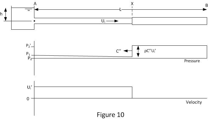
Figure 10 shows the condition after the forth reflection. The cycle has now began to repeat however the water hammer pressure is now reduced a little from P2 (figure 2) to P2’. This reduction in pressure has two causes. The fluid velocity has been reduced due to energy losses.
The sonic velocity C’’ may be less than the original sonic velocity C. If during the previous stages shown in figures 8 and 9 any gas was liberated from the fluid then this gas volume will have been reduced, however it takes time for the gas to be completely reabsorbed so there is likely to be small residual gas bubbles in the fluid. These gas bubbles will reduce the fluid bulk modulus so reducing the sonic speed.
Over a number of cycles the water hammer will eventually peter out. The pipe pressure will end up at P1 and the flow will stop oscillating.