When a liquid or gas flows along a pipe, friction between the pipe wall and the liquid or gas causes a pressure or head loss. This pressure or head loss is an irreversible loss of the fluids potential energy. Calculating this loss is fundamental to the design of any pipeline system.
The relationship between pressure and head is defined by the following formula
P= ρgh
Where
P is pressure (N/m2)
ρ is density (kg/m3),
g is gravitational acceleration (9.81 m/s2)
h is head (m).
When working with liquids it is usually better to calculate the friction loss as a head loss, as this makes the hydraulic calculations simpler. For gas flow a constant density cannot be defined so it is simpler to calculate the friction loss as a pressure.
The head loss in a length of pipe is given by the Darcy equation
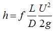
Where
f is the friction factor
L is the pipe length (m)
U is the fluid mean velocity(m/s)
D is the pipe diameter or the hydraulic diameter (m).
The hydraulic diameter is defined as
D= 4 x cross-sectional area / wetted perimeter.
For a standard circular pipe the hydraulic diameter is the same as the actual pipe diameter.
To determine the friction factor the Reynolds number needs to be calculated first. The Reynolds number is defined as
Re=UD/ ν
Where ν is the kinematic viscosity
The Reynolds number is the ratio of inertia forces to viscous forces. For Reynolds numbers up to 2000 the flow is normally considered to be laminar, above 3000 the flow is turbulent, at Reynolds numbers between 2000 and 3000 the flow is in a critical zone, predicting the friction factor in the critical zone is difficult because it is not obvious if the flow should be treated as laminar or turbulent.
For laminar flow conditions the friction factor
![]()
For turbulent flow the friction factor
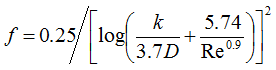 (Note: use base 10 log)
where k is the pipe wall roughness value(m).
Table of Roughness Values , k (mm)
| mm | |
| Smooth Pipes | |
| Drawn brass, copper, aluminium | 0.0025 |
| Glass, plastic, Perspex, fibreglass | 0.0025 |
| Steel Pipes | |
| New smooth pipes | 0.025 |
| Centrifugally applied enamels | 0.025 |
| Mortar lined, good finish | 0.05 |
| Mortar lined, average finish | 0.1 |
| Light rust | 0.25 |
| Heavy brush asphalts, enamels and tars | 0.5 |
| Heavy rust | 1.0 |
| Water mains with general tuberculations | 1.2 |
| Concrete pipes | |
| New, unusually smooth concrete with smooth joints | 0.025 |
| Steel forms, first class workmanship with smooth joints | 0.025 |
| New, or fairly new, smooth concrete and joints | 0.1 |
| Steel forms, average work workmanship, smooth joints | 0.1 |
| Wood floated or brushed surface in good conditions with good joints | 0.25 |
| Eroded by sharp materials in transit marks visible from wooden forms | 0.5 |
| Precast pipes, good surface finish, average joints | 0.25 |
| Segmentally lined conduits in good ground conditions with expanded wedge block linings | 1.0 |
| Segmentally lined conduits in other conditions | 2.0 |
| Other pipes | |
| Sheet metal ducts with smooth joints | 0.0025 |
| Galvanised metals, normal finish | 0.15 |
| Galvanised metals, smooth finish | 0.025 |
| Cast iron, uncoated and coated | 0.15 |
| Asbestos cement | 0.025 |
| Flexible straight rubber pipe with a smooth bore | 0.025 |
| Mature foul sewers | 3.0 |
Fluid Densities and Kinematic Viscosities of some fluids and gases
| Fluid | Density (ρ) kg/m3 | Kinematic viscosity (ν) m2/s |
| Hydrogen | 0.09 | 1.1 x 10⁻⁴ |
| Air | 1.2 | 1.5 x10⁻⁵ |
| Crude oil | 860 | 1.0 x 10⁻⁵ |
| Jet A1(-40oC) Kerosene | 851 | 9.5 x 10⁻⁶ |
| Jet A1(0oC) Kerosene | 823 | 2.5 x 10⁻⁶ |
| Jet A1(50oC) Kerosene | 786 | 1.0 x 10⁻⁶ |
| Water (0oC) | 999.8 | 1.79 x 10⁻⁶ |
| Water (4oC) | 1000 | 1.52 x 10⁻⁶ |
| Water (10oC) | 999.7 | 1.31 x 10⁻⁶ |
| Water (15oC) | 999.1 | 1.14 x 10⁻⁶ |
| Water (20oC) | 998 | 1.0 x 10⁻⁶ |
| Water (30oC) | 996 | 0.80 x 10⁻⁶ |
| Water (40oC) | 992.1 | 0.66 x 10⁻⁶ |
| Sea Water (0oC) | 1030 | 1.73 x 10⁻⁶ |
| Sea Water (15oC) | 1027 | 1.46 x 10⁻⁶ |
| Sea Water (30oC) | 1022 | 0.85 x 10⁻⁶ |
| Mercury | 13600 | 1.1 x 10⁻⁷ |
The information and data provided on this site are for information only. Fluid Mechanics Ltd does not guarantee the validity of any information provided. If you have a specific hydraulic problem then please contact us for technical advice.