Introduction
This paper describes our patented method of near isothermal compression and expansion of gases. In this paper the term isothermal means a system that approaches isothermal or is more isothermal than adiabatic. In any real machine it is not possible to have a truly isothermal or adiabatic process but this paper describes a practical method of approaching isothermal.
The paper mainly describes the isothermal process in terms of gas compression, as this will generally be the more common application but the process is equally applicable to gas expansion.
Isothermal compression is significantly more energy efficient than adiabatic compression, but with the current standard compressor technologies isothermal compression is not possible as the compression process happens so fast. In most compressors, compression is almost 100% adiabatic.

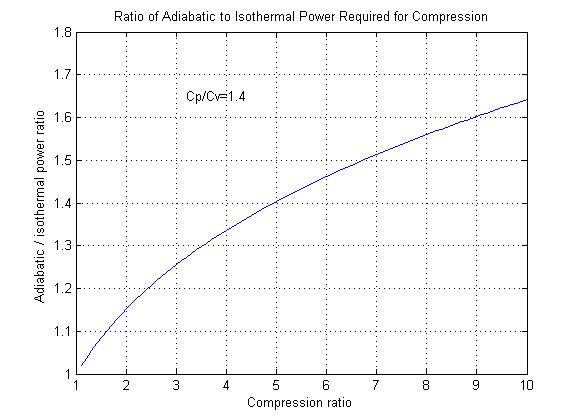
Figure 1
Figure 1 shows the additional power required to compress a gas adiabatically in comparison to isothermal compression.

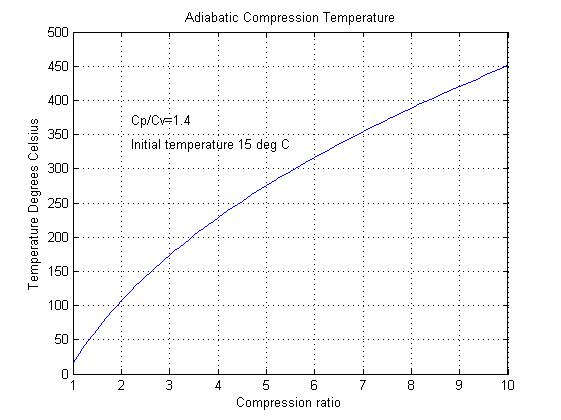
Figure 2
Adiabatic compression can also raise the significantly as shown in figure 2. This figure shows how the temperature rises with increased pressure ratio when the starting temperature is 15OC. This temperature rise can effectively limit the maximum compression ratio. For example in a gas turbine the maximum compression ratio is limited by the maximum allowable compressor blade temperature.
The most common way to negate the two effects of increased power and temperature is to use multistage compressors with inter-stage cooling, but with even relatively modest compression ratios the additional power requirements can be significant. The multi stage compression process also adds additional cost and losses, and the inter-stage gas temperature will be higher than the initial gas temperature, so limiting the efficiency gains of multistage compression.
The Isothermal Compressor
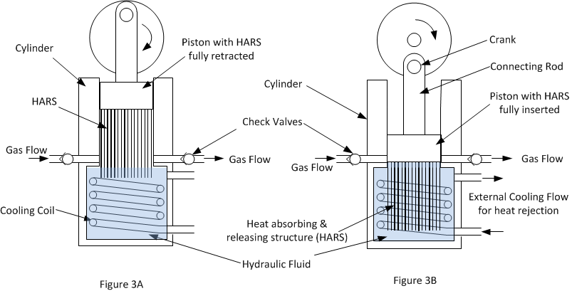
Figures 3A and 3B below shows schematically the basic concept of the new method of compression. In figure 3A the piston is at the end of the suction stroke about to start compression and in figure 3B the compression stroke has just been completed.

The essential new feature to make the compressor isothermal is a heat absorbing and releasing structure (HARS) attached to the piston which is inserted into the hydraulic fluid (usually water) during the compression stroke.

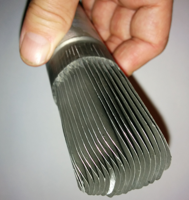
Figure 4
Figure 4 above shows a typical arrangement of the HARS. This specimen was used on Fluid Mechanics test rig.
In figure 4 the HARS is made from 0.15mm sheets of aluminium. Each sheet is at 2mm spacing and is held in position on the end of the piston with an epoxy resin moulding. Each of the sheets of aluminium is curved around the same centre, as this gives them much higher stiffness, so they are not deflected by hydraulic or other loads as they move in and out of the hydraulic fluid at speed.
During compression the gas is contained inside the HARS. The HARS has a large surface area and in the configuration shown in figure 4 the average distance the gas molecules are from the HARS surface is only 0.5mm. The thermal heat capacity of the HARS is significantly higher than the gas, so as the gas is compressed the heat of compression is rapidly transferred into the HARS, thus stabilising the gas temperature and providing isothermal compression.
The HARS is subsequently cooled by the hydraulic fluid in the bottom of the cylinder and then an external cooling circuit is used to cool this fluid.
Unlike other isothermal compressor with this new method the fluid is almost stationary and held in the bottom of the cylinder by gravity, and it is the HARS attached to the piston which moves in and out of the fluid. The HARS is designed such that the sheets that make up the HARS are parallel to the direction of travel of the piston, this allows the free flow of the hydraulic fluid in and out of the HARS with the minimum hydraulic resistance. These two design features allow the device to operate at relatively high speeds. The piston shown in figure 4 has been successfully operated at speeds up to 1500rpm .
3 Sep 2015

Pingback: Why Is Isothermal Compression More Efficient - captainraoul
Pingback: MKsOrb.Com